Configure a Numato Board
Configure a numato board to integrate Numato GPIO Peripheral Modules into your machine:
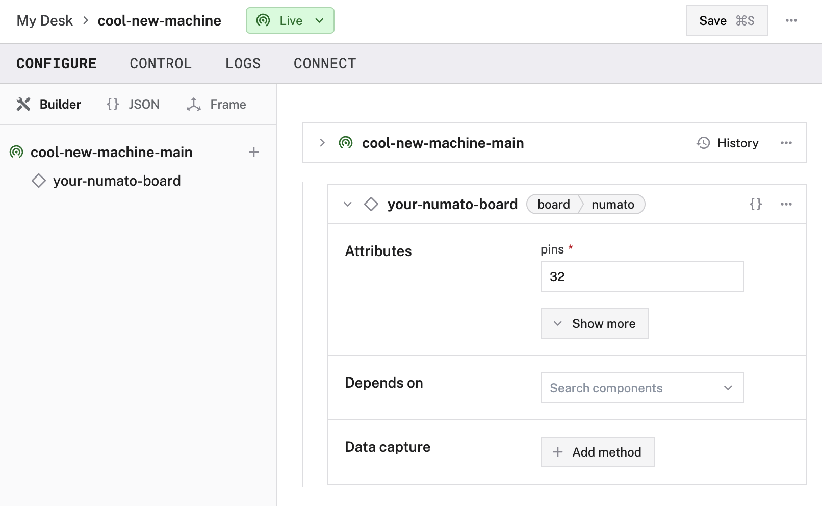
Navigate to the CONFIGURE tab of your machine’s page in the Viam app.
Click the + icon next to your machine part in the left-hand menu and select Component.
Select the board type, then select the numato model.
Enter a name or use the suggested name for your board and click Create.

Edit the attributes as applicable to your board, according to the table below.
{
  "components": [
    {
      "name": "<your-numato-board>",
      "model": "numato",
      "type": "board",
      "namespace": "rdk",
      "attributes": {
        "pins": <number>,
        "analogs": [
          {
            "name": "<your-analog-reader-name>",
            "pin": "<pin-number-on-adc>",
            "spi_bus": "<your-spi-bus-index>",
            "chip_select": "<chip-select-index>",
            "average_over_ms": <int>,
            "samples_per_sec": <int>
          }
        ]
      },
      "depends_on": []
    }
  ]
}
The following attributes are available for numato boards:
| Name | Type | Required? | Description |
|---|---|---|---|
pins | int | Required | Number of GPIO pins available on the module. |
analogs | object | Optional | Attributes of any pins that can be used as Analog-to-Digital Converter (ADC) inputs. See configuration info. |
Attribute configuration
Configuring these attributes on your board allows you to integrate analog-to-digital converters into your machine.
analogs
An analog-to-digital converter (ADC) takes a continuous voltage input (analog signal) and converts it to an discrete integer output (digital signal).
ADCs are useful when building a robot, as they enable your board to read the analog signal output by most types of sensors and other hardware components.
To integrate an ADC into your machine, you must first physically connect the pins on your ADC to your board.
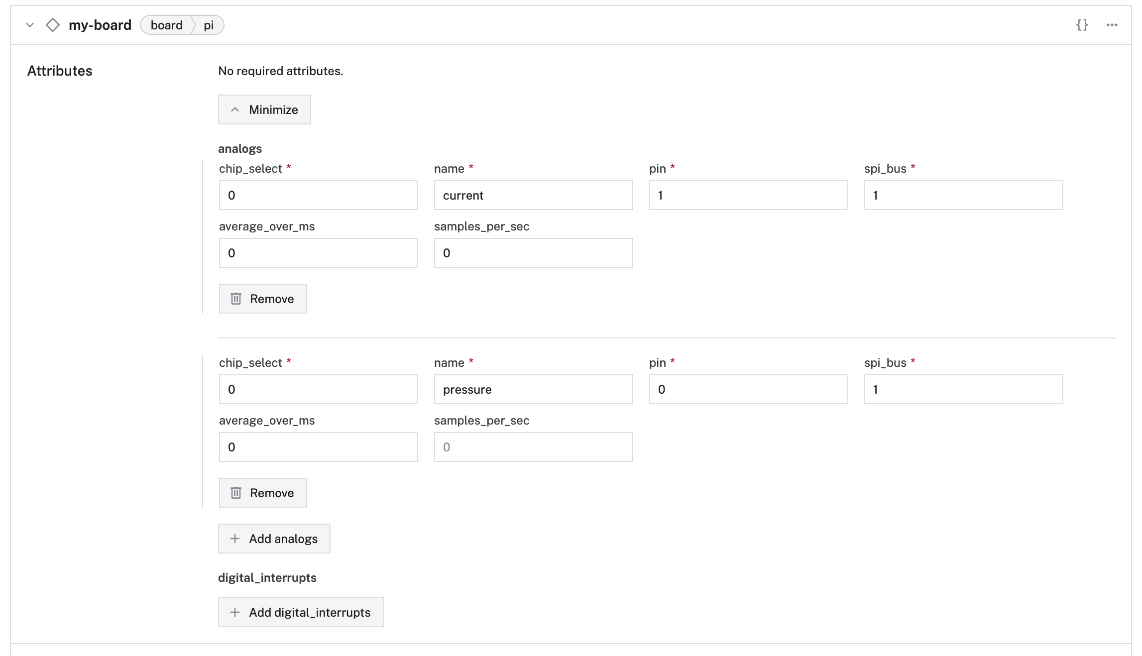
Then, integrate analogs into the attributes of your board by following the Config Builder instructions or by adding the following to your board’s JSON configuration:
On your board’s panel, click Show more, then select Add analog. Assign a name to your analog and then fill in the required properties outlined below.

// "attributes": { ... ,
"analogs": [
  {
    "name": "<your-analog-reader-name>",
    "pin": "<pin-number-on-adc>",
    "spi_bus": "<your-spi-bus-index>",
    "chip_select": "<chip-select-index>",
    "average_over_ms": <int>,
    "samples_per_sec": <int>
  }
]
{
  "components": [
    {
      "model": "pi",
      "name": "your-board",
      "type": "board",
      "attributes": {
        "analogs": [
          {
            "name": "current",
            "pin": "1",
            "spi_bus": "1",
            "chip_select": "0"
          },
          {
            "name": "pressure",
            "pin": "0",
            "spi_bus": "1",
            "chip_select": "0"
          }
        ]
      }
    }
  ]
}
The following properties are available for analogs:
| Name | Type | Required? | Description |
|---|---|---|---|
name | string | Required | Your name for the analog reader. |
pin | string | Required | The pin number of the ADC’s connection pin, wired to the board. This should be labeled as the physical index of the pin on the ADC. |
chip_select | string | Required | The chip select index of the board’s connection pin, wired to the ADC. |
spi_bus | string | Required | The index of the SPI bus connecting the ADC and board. |
average_over_ms | int | Optional | Duration in milliseconds over which the rolling average of the analog input should be taken. |
samples_per_sec | int | Optional | Sampling rate of the analog input in samples per second. |
Test analogs
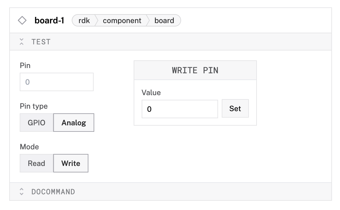
Once you have configured your analogs, open the board’s TEST panel on the CONFIGURE or CONTROL tabs to monitor analogs. The numbers displayed next to each analog name represent the digital signal received from the analog inputs.

Have questions, or want to meet other people working on robots? Join our Community Discord.
If you notice any issues with the documentation, feel free to file an issue or edit this file.
Was this page helpful?
Glad to hear it! If you have any other feedback please let us know:
We're sorry about that. To help us improve, please tell us what we can do better:
Thank you!